Introduction
The very nature of agile software development is such that requirements change over time. This, in turn, translates into the need to track requirements constantly and meticulously. This can prove to be a hassle in the case of long-standing projects with multiple stakeholders. There is only so much documentation possible within scrum teams, and constantly reading through changes can lead to fatigue and a warped understanding.
This is where visualization comes in. The use of visualization techniques in discussing business scenarios makes the entire process less tedious and more intuitive, and serves as a handy tool for collaboration.
In this case study, we showcase how we handled complex, changing requirements using Unified Modeling Language (UML) diagrams to capture workflows.
The nature of the requirement
In this particular case, the end customer wanted a tracking system to handle their orders through various stakeholders. These orders were typically for custom office supplies and needs. A catalog was to be made available, through which registered customers could select and customize items per their needs. They could then place orders which would be fulfilled by vendors specializing in such customizations.
Their customer base was huge and spread across various organizations, and vendors had to be mapped in such a way that order fulfillment could happen within the agreed upon SLA.
It was hard to zero in on the workflow accurately at the initial stages. But through successive iterations, we were able to get a firm grasp of the workflow.
a) First Iteration
- Customer places order
- Order assigned to vendor
- Customer approves of the order and assigns it to the manager
- Order approved by manager
- Order is fulfilled by the vendor
- Order closed
See the diagram Iteration 1.0 below.
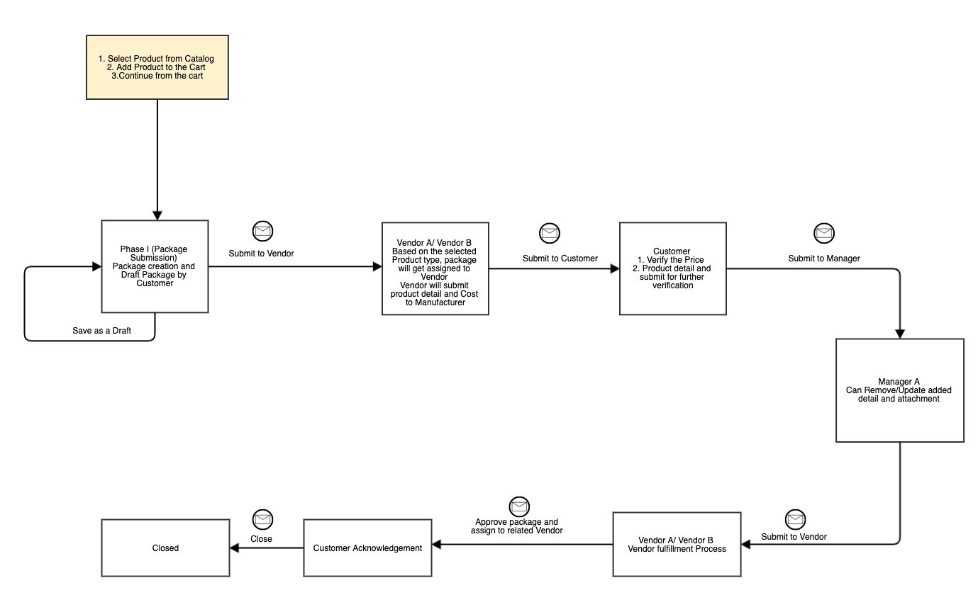
Iteration 1.0 of the workflow as a UML diagram
b) Second Iteration
The second iteration of requirements review involved the addition of more functionality to the workflow, in terms of a rejection mechanism, vendor fee and a separate order fulfillment cycle.
The workflow changed to:
- Customer places order
- Order assigned to vendor for providing cost plus fee
- Order assigned to customer
- Customer assigns order to manager for approval
- Manager can reject package to either of the vendors
- Vendors update the order with relevant information
- Manager approves order
- Vendor completes order through various stages of fulfilment (shipping, delivery, dispatch)
- Order closed
See diagram Iteration 2 below.
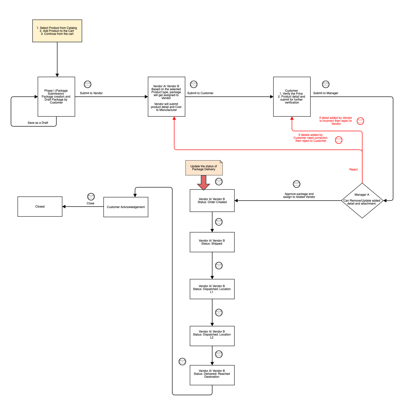
Iteration 2.0, where more functionality was added
c) Third Iteration
The third iteration of requirements review involved the addition of manufacturers and suppliers, and tracking of orders through them. We had to figure out how manufacturers and suppliers were mapped to the vendors, and further, how this would affect the workflow.
The workflow expanded to the one below:
- Customer places order
- Order passes through one vendor based on delivery location
- Order is assigned to a specified manufacturer based on the vendor assigned
- Order is assigned to a supplier based on the manufacturer
- Order assigned to customer
- Order assigned to manager
- Vendor completes order through various stages of fulfilment (shipping, delivery, dispatch)
- Order closed
See diagram Iteration 3.0 below.
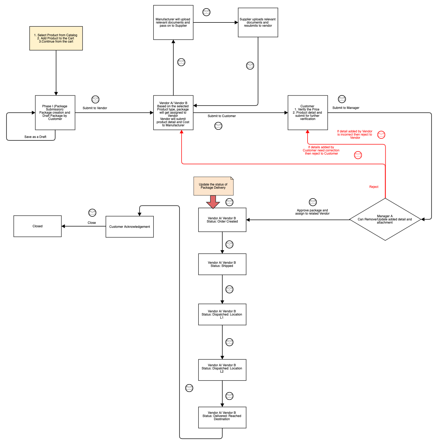
Iteration 3.0, involving manufacturers, suppliers, and order tracking
d) Fourth Iteration
Through further review with the relevant stakeholders, it was decided that the order delivery location decided which vendor would pick up the order. This meant that we had to restructure the entire vendor registration and assignment modules. The customer also wanted a mechanism where users could raise issues against orders, and this raised the need for a sub-workflow within the workflow, with rejection at various stages of the order fulfillment process.
- Customer places order
- Order passes through one vendor based on delivery location
- Order is assigned to a specified manufacturer based on the vendor assigned
- Order is assigned to a supplier based on the manufacturer
- Order assigned to customer
- Order assigned to manager
- Vendor works through the order through various stages of fulfilment (shipping, delivery, dispatch)
- Customer can raise an issue at any stage of fulfilment
- Order closed after issue resolution and the customer’s acknowledgement
See diagram Iteration 4 below.
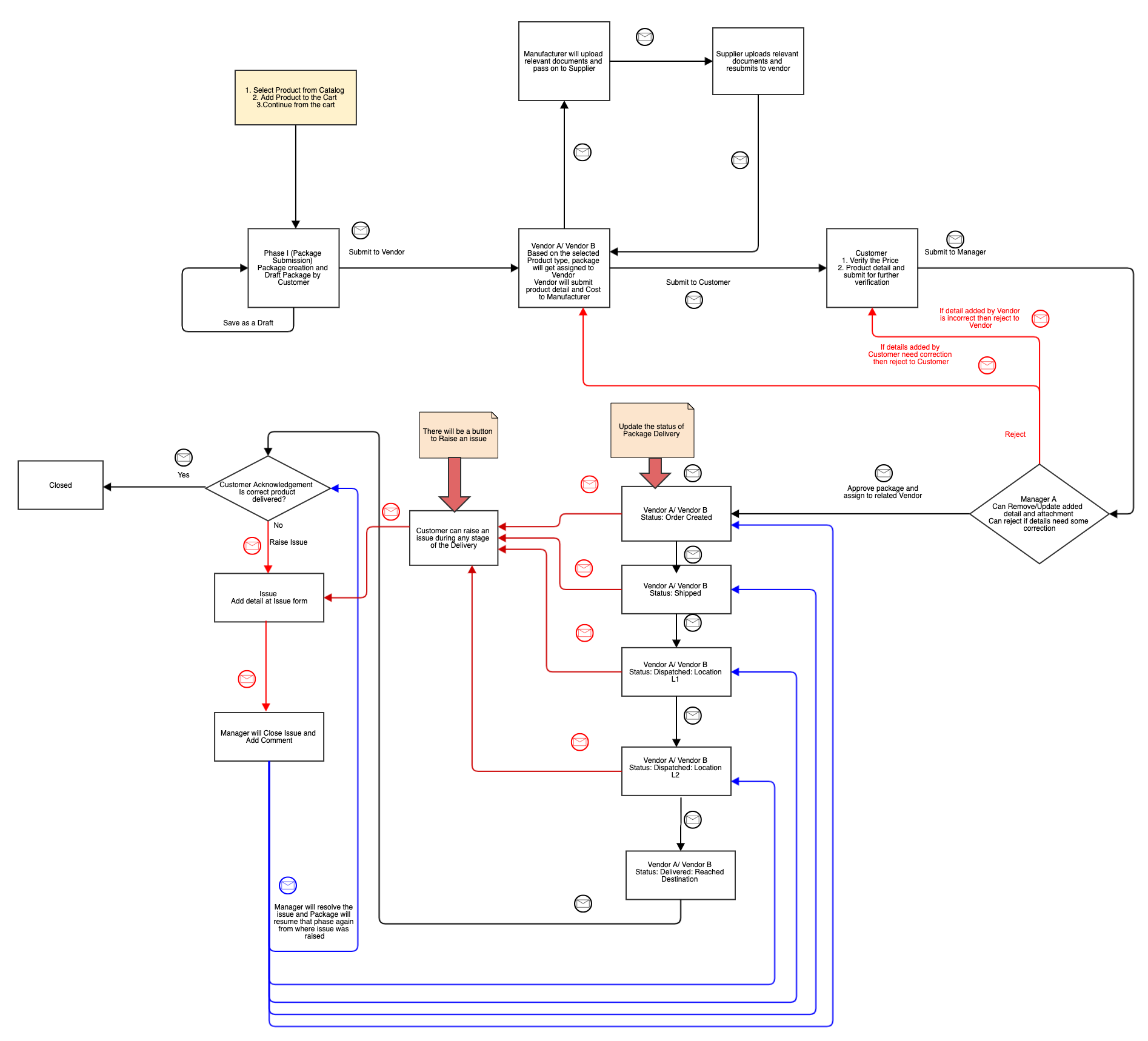
Iteration 4.0, which involved significant restructuring
During the initial phases of product discovery and development, we found it increasingly difficult to keep track of the changes for users and the impact each change would have on the overall workflow cycle. This was when we decided to recreate these workflows and their iterations as UML diagrams and use them as a tool to collaborate with the client and ask the right questions. Over time, the UML diagrams enabled us to envisage how the customer journey would be in real time and analyze impact. They also helped us maintain requirement versions and were an important tool for QA activities.
UML diagrams as a Business Analysis tool
Creating these UML workflow diagrams helped us review the requirements before even delving into the design/development phase. Through this review, we were able to question the various use cases that would be followed, the nature of different roles and any overlaps. As a result, we were able to clarify any ambiguities in requirements, and this ensured that we were on the right track to building software per the need of the client.
UML diagrams as a QA enabler
The QA team was able to draw test scenarios from these workflow diagrams, which further helped in detailing out test cases. We could validate the test coverage of all workflow state transitions by means of mapping the test cases to various nodes in the workflows. These diagrams also served as a ready reckoner for refreshing our knowledge and assisted us in explaining defects/misses in the workflow. Team communication over defect triages was simplified as we could use these diagrams as our requirement basis.
Over a period of time, as the requirements evolved, we ensured that we kept these diagrams updated. This helped us gain insights into future requirements for customers and/or to suggest improvements. We also started using this UML documentation of workflows as a knowledge transfer (KT) tool to onboard new resources.
Overall benefits
- Worked as a visual aid for conversations around product improvement
- Enabled quicker product discovery and served as an impact analysis tool
- Enabled quick onboarding of new project team members
- Effective demo/KT to client team members
- Worked as a static testing tool
- Assisted in test case preparation and test coverage validation
- Worked as a key visual aid to validate the workflow during test execution
- Living documentation of project needs
Conclusion
The visual representation of requirements enabled us to arrive at quicker decisions, align on our needs and priorities and ensured a smooth transition between various SDLC phases. Having visual aids for tracking agile requirements yielded us tangible results in the long run, and enabled us to build the product with a quicker turnaround time and in line with customer expectations.

Parita Patel, QA Engineer - L2
She loves singing and being around children and the elderly, and can’t stand the sight of a bug in her food! Off work, you’ll find her spending quality time with her family.
 We respect your privacy. Your information is safe.


Leave us a comment